Praktica BMS
AKA: Revue BC 2

Posted 9-27-'03
This camera manual library is for reference
and historical purposes, all rights reserved.
This page is copyright© by Butkus Camera Manual Site,  M. Butkus, NJ.
This page may not be sold or distributed without
the expressed permission of the producer
I have no connection with any camera company.

On-line camera manual library

Back to main on-line manual page

If you find this manual useful,
how about a donation of $3 to:


M. Butkus, 29 Lake Ave.,
High Bridge, NJ 08829-1701
and send your e-mail address
so I can thank you. 
Most other places would charge
you $7.50 for a electronic copy
or $18.00 for a hard to read Xerox copy.

This will help me to continue to host this site,
buy new manuals, and pay their shipping costs.

It'll make you feel better, won't it ?

If you use Pay Pal, use the link below.
Use the above address for a check, M.O. or cash.
If you use PayPal.. use the link below

Venmo  @mike-butkus-camera  Ph. 2083

butkus camera manual site

Click here for Camera Manual site

<<< IF YOU WOULD LIKE THIS OR ANY PDF FILE
PRINTED, BOUND AND MAILED TO YOU,
SEE THIS OUTSIDE COMPANY'S OFFER
>>>


Praktica BMS PDF straight from manual
Praktica BMS Bedienungsanleitung
Praktica BMS instrucciones para el uso


CLICK HERE FOR A Praktica BMS PDF
English VERSION OF THIS PAGE


CLICK HERE FOR A TRANSLATED
PRAKTICA BMS MODE D'EMPLOI


CLICK HERE FOR A TRANSLATED
PRAKTICA BMS Bedienungsanleitung


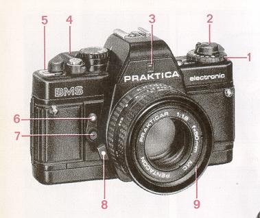
Requires a PB bayonet lens called a Prakticar
Not a Pentax K-mount

Praktica BMS

For more information on this camera, see this personal website

PRAKTICA BMS These instructions refer also to the PRAKTICA BM.
Only the information given
for the self timer is only applicable to the PRAKTICA BMS.


Praktica BMS parts 1.  Film speed dial
2.  Rewind button with crank
3.  Window for aperture setting reflection into viewfinder
4.  Winding lever
5.  Frame counter
6.  Winding /ever for self-timer
7.  Release button for self-timer
8.. Lens unlocking key
9.  Filter thread


Praktica BMS parts 10.  Aperture setting ring 
11.  Film speed index
12.  Battery check button
13.  Hot shoe with center contact
14.  Contact for dedicated computerized flash units
15.  Shutter speed dial
16.  Release button
17.  Cable release socket
18.  Shutter release lock
19.  Carrying lug
20.  Lens positioning mark
21. Depth-of-field scale
22.  Focusing ring


Praktica BMS parts 23.  Eyepiece with accessory holder 
24.  Shutter
25.  Film cartridge space
26.  Film sprocket
27.  Take-up spool
28.  Camera back


Praktica BMS parts 29.  Battery compartment lid with locking button 
30.  Rewind release button
31. Tripod socket
32. Plug-in frame {memo holder}

Technical features


· single-lens reflex 24mmx36mm frame size TTL light metering at full aperture through electronic aperture setting transfer.

· automatic shutter speed control from 1/1000s to 4s; aperture or shutter speed priority

· film speed range from ISO 12 to ISO 3200

· viewfinder information through LEDs in different colors

· shutter speeds from 1/1000s to 4s

· warning of overexposure and underexposure

· flash readiness

· battery check

· aperture setting reflected into viewfinder

· focusing system: Fresnel lens with diagonal triple wedge, microprism ring and ground glass ring

· Viewfinder image shows 95% of picture sides - electronic flash synchronization at 1/60s - PRAKTICA bayonet (flange focal length 44.4mm; inner diameter 48.5mm) - self-timer (approx. 8s) with release button - memo holder on camera back - power source: 6 V primary battery - light receiver: silicon photocell - measuring and control range: 0... 17EV at ISO 100 and aperture 1.4

- body dimensions: 138mmx87mmx49mm weight (body without battery): BMS 480 g, BM470g.

Praktica BMS parts


Praktica BMS parts

Inserting the battery - A 6V battery powers the whole electronic | system. Suitable are alkali-manganese, silver oxide and lithium batteries. Four button cells (e.g. LR 44) inserted in a sleeve (identification no.961 363) can also be used. Normally, a fresh battery will last for about 2 years. To insert the battery, turn the locking but- ' ton of the battery compartment lid (29) counterclockwise until the lid can be opened. Clean the contacts in the compartment and the battery Does using a dry cloth. Press the plus pole of the battery against the resilient contact (see the polarity marks on the inner side of the lid) and tip the battery in (Figure 1). Close the lid and lock it.  It is recommended to check the contact points of the battery and compartment from time to time and clean them, if necessary. The battery is sensitive to low temperatures and should be protected in a suitable manner. If the camera is not used for an extended period, take the battery out of the compartment.


Checking the battery

First press the release button (16) slightly and then button (12); see Figure 2. The battery is sufficiently charged if the LED indication is bright. The LEDs go out if the battery is spent. Check for about 1 second.

In the "B" setting the battery cannot be checked.

Opening the camera back 
Pull the rewind button (2) up to unlock the camera back (Figure 3). Open the back fully -the frame counter resets to start position.

Loading the film
Place the film cartridge into the cartridge space (25). Push in the rewind button (2); turn it, if necessary.

Thread at /east 1 cm of the film leader into the slit of the take-up spool (27). Then turn the knurled spool plate of the take-up spool towards the shutter until the sprocket teeth engage the perforations on both sides of the film (Figure 4).

Closing the camera back
Grip the back in the middle of the latch side and press it against the camera body until it clicks in.


Preparing for shooting
The winding lever (4) can be swiveled a short way without initiating winding. This ready position is ideal for shooting fast sequences. Swing the winding lever fully out, bring it back and release the shutter by pressing the release button (16). Repeat this as often as is required for the frame counter (5) to read "1 "

Proper film transport can be checked by looking at the rewind button (2): it should turn when the winding lever (4) is operated.

Setting the film speed
Lift the film speed dial (1) and turn it until the ISO/ASA film speed printed on the film pack (see the ISO/ASA and DIN film speed reference table below) faces the index (11); see Figure 5. As a memory aid, you may plug the torn-off flap of the film pack into the memo holder (32).

ISO/ASA and DIN film speed see table page 16

Working ranges
 
With TTL light metering at full aperture, the camera can cover the following shutter speed ranges for the various film speeds. Table below

ISO F 2.8 F4 F5.6 F8 F11 F16 F22
100 4 - 1/1000 4 - 1/1000 4 - 1/1000 4 - 1/1000 4 - 1/1000 4 - 1/500 4 - 1/250
200 4 - 1/1000 4 - 1/1000 4 - 1/1000 4 - 1/1000 4 - 1/1000 4 - 1/1000 4 - 1/500
400 2 - 1/1000 4 - 1/1000 4 - 1/1000 4 - 1/1000 4 - 1/1000 4 - 1/1000 4 - 1/1000
800 1 - 1/1000 2 - 1/1000 4 - 1/1000 4 - 1/1000 4 - 1/1000 4 - 1/1000 4 - 1/1000
1600 1/4 - 1/1000 1 - 1/1000 2 - 1/1000 4 - 1/1000 4 - 1/1000 4 - 1/1000 4 - 1/1000

3200

1/4 - 1/1000 1/2 - 1/1000 1 - 1/1000 2 - 1/1000 4 - 1/1000 4 - 1/1000 4 - 1/1000


Setting the shutter speed 

Turn the shutter speed dial (15) until the desired speed faces the index ("125-in Figure 6). The LED next to "125" will flash when the release button is slightly pressed.

4s to 1/15s - for shots where the object brightness is low, a tripod is needed

1/30s to 1/1000s - for shots where the object brightness is sufficient

Symbol 60 Praktica BMS flash - for shots with an electronic flash gun (time is mechanically formed, also without a battery)


Setting the aperture

Turn the aperture setting ring (10) until the desired a aperture matches the index mark on the lens mount (Figure 7). The aperture setting is reflected into the lower part of the viewfinder.

Recommended apertures for a film speed of ISO 80:

  Aperture
Full sunlight 

8. . . 11

Overcast 4 . . . 5.6
Close-ups not less than 8


The aperture can also be preselected on the basis of the depth of field desired for the subject taking into account the shutter speed information in the finder so as to avoid blurring. A small aperture means a great depth of field, whereas a large aperture gives a shallow depth.

Focusing
Focusing is possible with the triple wedge, microprism ring and ground glass ring (Figure 8).

A Triple wedge
The triple wedge system allows highly accurate focusing. Optimum sharpness is obtained when contours and lines flow naturally. The object focused on is out of focus when the contours of the center wedge are out of alignment.

B Microprism ring
The subject is in proper focus when the image in this field is clear and does not flicker.

C Ground glass ring
This focusing ring is of advantage in photomacrography and photomicrography, but also when the lens used has a small relative aperture (f-numbers greater than 4). The image in the ring shall be clear and sharp.


Infrared shots
Infrared shots call for a slight correction of the distance setting: after focusing in the normal way, match the distance so determined with the infrared index on the lens barrel.
The arrow in Figure 7 points to the infrared index.

Depth-of-field indication
The depth-of-field limits for the aperture set can be read from the depth-of-field scale (21) on the lens (Figure 7).
Example: distance 3 m, aperture 8 - depth of field stretches from about 2m to 5m

Semi-automatic mode
There are two possibilities:

1. Shutter speed is preselected, aperture is adapted (preferable with good lighting conditions and normal shots)

2. Aperture is preselected, shutter speed is adapted (favorable with poor lighting conditions when a certain depth of field is required)

Shutter speed is preselected 
Set the desired time by turning the shutter speed dial (15). Press the release button (16) halfway down to switch on the camera electronics. Check the shutter speed by means of the finder LEDs.
While the LED pertinent to the preselected shutter speed flashes, another LED, which shines permanently, indicates the shutter speed required for the available lighting conditions, film speed and aperture. Two LEDs may light in the case of intermediate values. To set the camera for correct exposure, turn the aperture setting ring (10) until the flashing LED is permanently on. The aperture so set can be seen at the lower edge of the viewfinder.

Apertures preselected
Set the desired aperture by turning the aperture setting ring (10). Switch on the electronic system by pressing the release button (16) halfway down. The shutter speed indication will be as described above, i.e. the LED for the shutter speed set will flash, whereas the shutter speed actually needed for a correct exposure is indicated by a permanently lit LED. Turn the shutter speed dial until the flashing LED moves toward the permanently lit one, and finally coincides with the latter.
There is no LED display in the "B" setting. The flash synchronization time is mechanically formed, making it possible to photograph at 1/60s, or Praktica BMS parts. All the other shutter speeds, inclusive of "B" are electronically formed.
If the 1/1000s to 4s shutter speed range is exceeded in any one direction, LED signals are given. Overexposure is indicated by the OVER LED flashing, underexposure by the UNDER LED flashing or by two LEDs shining permanently.


Release button
To facilitate operation, several functions have been built into the release button (16). Pressing it slightly down until resistance is felt switches on the electronics and the shutter speed/flash readiness LEDs (the latter when computerized flash guns are used).
After making the required exposure settings and winding the shutter pressing the release button further down causes the shutter to fire. Letting go of the button switches the electronics off. Relieving the pressure from the release button during long exposure times has no effect on the exposure; the electronics will not switch off until the shutter has completed its operation.

Locking the release button
The release button lock (8) is used to prevent unintentional shutter release and unnecessary power consumption which would occur when the release button is inadvertently pressed, no matter if the shutter is wound or not Just turn the lock clockwise to arrest the release button (Figure 9). Unlock by turning it counterclockwise. Attention ! Do not lock the button when it is pressed down.

Self-timer
Wind the shutter and swing the winding lever for the self-timer (6) down as far as it will go. Press the release button /7) of the self-timer (Figure 10). The shutter will fire after a delay of about 8s. Attention! Do not wind the shutter while the self timer mechanism is running.

Flash photography
If the available light is insufficient, for example, to take indoor shots, a flash unit is recommended to be used. All electronic flash units can be plugged on, computerized or not, if they fit on this camera model.
Just plug the flash unit into the hot shoe (13) to connect it to the camera.
Set the shutter speed dial (15) to "60" When the release button (16) is slightly pressed, the LED next to "60" will flash. At the same time, the shutter speed is indicated.
When attaching simple electronic flash guns, use the guide number to determine the aperture or distance.
In addition to the shutter speed information, flash readiness of camera and flash unit is indicated when a dedicated computerized flash gun is plugged on. A green LED will light next to the flash symbol in the finder, also in the "B" setting.


Changing the film
After shutter operation the frame counter (5) shows the number of frames exposed. When the maximum number of frames on the film (red markings at 20 and 36) are exposed, the film must be changed.
Press in the rewind release button (30), fold out the rewind crank (2) and turn it not too fast in the direction of the arrow, i. e. clockwise (Figure 11) until increased resistance followed by easy turning is felt, which indicates that the film has slipped out of the take-up spool. Then pull the rewind button up to unlock the camera back, and take the film cartridge out. Do not change the film in full sunlight
If more frames have been exposed than are printed on the film pack, it may happen that the winding lever cannot be swung fully out Do not use force in this case but rewind the film as described above.

Changing the lens
Press the unlocking key (8), turn the lens counterclockwise and take it out of the body (Figure122).
Insert the PRAKTICAR lens so that the red marks (8/20) on camera and lens match. Then press the lens against the camera body and turn it clockwise until it clicks in.
All original PRAKTICA lenses with the M 42x1 screw-in thread can be attached to this model by means of the PRAKTICA adapter. With the exception of the light measurement, which is made at working aperture. there are no restrictions in camera operation when a screw-in lens is used.

Care of the camera
· Protect the camera from blows, knocks, dust and moisture.

· Clean the cartridge and spool space, film track and camera back from time to time using a soft brush.

· Do not use organic solvents like spirit or varnish thinner for cleaning the camera.

· Keep aggressive vapors away from camera and lens.

· Remove any finger prints from the lens and eyepiece surfaces with lens cleaning tissue.

· Do not touch the mirror, field lens or shutter curtains with your fingers as the resulting contamination can only be removed by a service workshop.

· Use an optician's (soft) brush to remove dust or blow it off with a rubber ball.

· Do not subject the camera to very high or low temperatures. For example, avoid putting it on the hat rest of a car in full sunlight

The camera, and especially the batteries, should be protected in a suitable way against deep temperatures.

· When using the camera near the sea or on the beach, protect it against salt water, mist and sand.

· Avoid subjecting the camera to sudden temperature changes as these may lead to water condensation and, consequently, corrosion.

· In case of defects, do not try to repair the camera yourself but call on a service workshop.

Please follow the above instructions. Improper use of the camera may lead to defects which are not covered by our guarantee.

Further development of the PRAKTICA BMS may result in minor deviations from the details contained herein.