Ricoh XR-X3000
This camera manual library is for reference
and
historical purposes, all rights reserved.
This page is copyright
© by
 ,
M. Butkus, NJ.
,
M. Butkus, NJ.
This page may not be sold or distributed
without the
expressed permission of the producer
I have no connection with any camera company.
On-line camera manual library
If you find this manual useful,
how about a donation
of $3 to:
M. Butkus, 29 Lake Ave.,
High Bridge, NJ 08829-1701
and send your
e-mail address
so I can thank you.
Most other places would charge
you $7.50 for a electronic copy
or $18.00 for a hard to read Xerox copy.
This will help me to continue to host this site,
buy new manuals,
and pay their shipping costs.
It'll make you feel better, won't
it ?
If you use Pay Pal, use the link below.
Use the above address for a check, M.O. or cash.
www.PayPal.me/butkus
Venmo @mike-butkus-camera
Ph. 2083
<<<
IF YOU WOULD LIKE THIS OR ANY PDF FILE
PRINTED, BOUND AND MAILED TO YOU,
SEE THIS OUTSIDE COMPANY'S OFFER >>>
Back to main camera manual page
CLICK HERE FOR Ricoh XR-X 3000 PDF
VERSION MADE FROM HTML PAGE
- Better printing -
Posted on 6-20-02
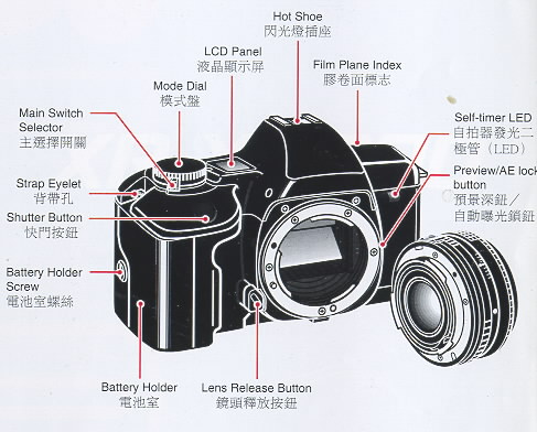
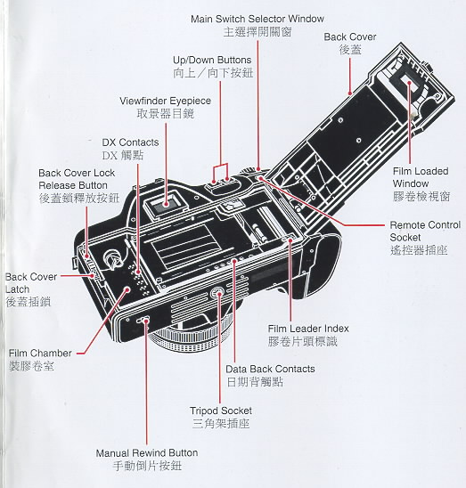
I. LOCATING THE CONTROLS
When reading this manual, refer to "locating the controls" (fold out the
front and back covers)
Reading the Exposure Indicator The exposure indicator is
displayed in the viewfinder display and the exposure compensation value is
displayed on the LCD panel in the following conditions:
· In Manual operation
· When the exposure compensation has been set.
· When the exposure compensation is being set.
In Manual operation or for exposure compensation, the exposure indicator in
the viewfinder display indicates the difference between the correct exposure
value (EV) and the current exposure compensation setting.
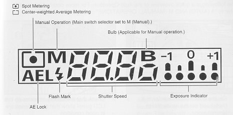
The * mark flashes when the value exceeds -1 EV or +1 EV.
Exposure compensation can be set within the range of +/- 4 EV in 0.5 EV
increments. The shutter speed in the viewfinder display flashes when the
current exposure setting is beyond the exposure metering range. However, the
overexposure or underexposure can still be taken deliberately to capture a
particular creative effect. Nevertheless, to avoid incorrect exposure,
select a larger or smaller aperture, select a faster or slower shutter
speed, or use a flash unit as necessary.
IV. QUICK GUIDE IN AUTO OPERATION
The following is a quick overview of the Auto Operation. For more detailed
information, refer to "A (AUTO) AND M (MANUAL) OPERATIONS" on page 17.
V. CONTENTS
1. LOCATING THE CONTROLS 3
2. FUNCTION MAP 4
3. LCD INFORMATION 6
Viewfinder Display 7
Reading the Exposure Indicator 7
4. QUICK GUIDE IN AUTO OPERATION 8
5. CONTENTS 10
6. ATTACHING THE STRAP 12
7. INSERTING THE BATTERIES 12
8. MOUNTING AND REMOVING THE LENS 13
9. MAIN SWITCH SELECTOR ; 14
10. MONITORING THE CONDITION OF THE BATTERIES 14
11. LOADING THE FILM 15
12. SETTING THE FILM SPEED AUTOMATICALLY 16
DX Films 16
Non-DX Films 16
A (AUTO) AND M (MANUAL) OPERATIONS
13. MAIN SWITCH SELECTOR--UA/M 17
Auto Power Off Function 18
14. A (AUTO) OPERATION 18
15. M (MANUAL) OPERATION 19
Bulb Function 20
16. HOLDING THE CAMERA 21
17. FOCUSING 22
Types of Focusing 22
18. SHOOTING 23
19. REWINDING THE FILM 24
Midroll Rewind 24
MODES
20. SETTING THE MODES 25
21 SELF-TIMER MODE 26
22. MULTI EXPOSURE MODE 27
23. AUTO BRACKETING MODE 28
24. CONTINUOUS SHOOTING MODE 28
25. NORMAL MODE 29
26. EXPOSURE METERING USER SETTING MODE 29
27. PREVIEW/AK LOCK USER SETTING MODE 30
28. ISO USER SETTING MODE 32
29. EXPOSURE COMPENSATION 33
Shooting in Backlit Conditions 33
Dominantly White Subjects 34
Dominantly Dark-colored Subjects 34
FLASH PHOTOGRAPHY
30. FLASH PHOTOGRAPHY WITH SL-303P, SL-403P 36
31. FLASH PHOTOGRAPHY WITH FLASH UNITS OTHER THAN RICOH 37
OTHERS
32. INFRARED FILM 38
33. DIOPTRIC LENSES 38
34. INTERCHANGEABLE VIEWFINDER SCREENS 39
35. RELEASE SWITCH 39
36. CARE OF BATTERIES 40
37. DATA BACK 7 40
38. PROPER CARE OF YOUR CAMERA 44
39. MAJOR SPECIFICATIONS 45
VI. ATTACHING THE STRAP
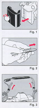 |
1. Remove the battery holder by turning the battery holder
screw counterclockwise with a coin. (Fig. 1)
2. Slip the viewfinder cap and shoulder pad onto the strap.
(Fi 9. 2)
3. Run the strap through the strap eyelet as shown. (Fig. 3)
|
 |
4. Secure the battery holder to the camera body by turning
the battery holder screw clockwise with a coin. (Fig. 4)
5. Adjust the strap length as desired.
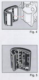
VII. INSERTING THE BATTERIES
1. Remove the battery holder.
2. Insert four new M-size alkaline batteries and make sure
that the + and - on the batteries are aligned according to the
polarity diagram inside the battery holder. (Fig. 5)
|
<<< update - I have been told a Olympus eyecup and other accessories will
work on XR cameras >>>
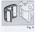 |
3. Secure the battery holder to the camera body by turning
the battery holder screw clockwise with a coin. (Fig. 6)
Notes on Batteries
· The condition of the batteries should be monitored frequently.
For more information, refer to "MONITORING THE CONDITION OF THE
BATTERIES" on page 14.
· Be sure to replace all four batteries at once. Replace with
the same brand of batteries.
· Do not use AA-size lithium batteries.
|
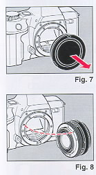 |
VIII. MOUNTING AND REMOVING THE LENS
1. Remove the camera body cap. (Fig. 7)
2. Align the red dot on the camera with the red dot An the
lens and mount the lens on the camera. (Fig. 8)
|
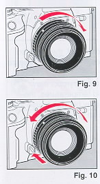 |
3. Turn the lens in the direction shown by the arrow until it
clicks into place. (Fig. 9)
· If the lens is to be removed from the camera for a certain
period of time, use the camera body cap to avoid dust and
foreign particles from entering your camera. Likewise, use the
front and rear lens caps to protect your lens also.
4. To remove the lens, press the lens release button, then
turn the lens in the direction shown by the arrow. (Fig. 10)
· For best results, use Ricoh lenses only. Optimum
performance of the camera may be compromised by using other
lenses.
|
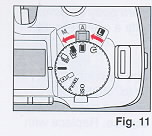 |
VI. MAIN SWITCH SELECTOR
1. Set the main switch selector to A (Auto) or M (Manual). (Fig.
11 )
· If the camera is left unattended for about 30 seconds, the
power switches off automatically and the display on the LCD
panel disappears. The Auto Power Off function prevents
unnecessary waste of the battery power. The current information
contained in the camera memory is retained.
Lightly press the shutter button to turn on the power and update
the LCD panel. For maximum battery life, always set the
main switch selector to L (Lock) when the camera is not used.
|
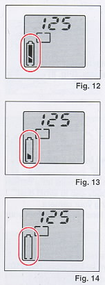 |
X. MONITORING THE
CONDITION OF THE BATTERIES
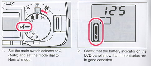
When the main switch selector is set to A (Auto) or M
(Manual), the battery condition is displayed on the LCD panel.
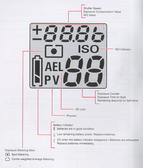
1. Batteries are in good condition when the I symbol appears
on the LCD panel. (Fig. 12)
2. When the batteries are nearly exhausted, the a symbol is
displayed on the LCD panel. (Fig. 13) Replace with four new
M-size alkaline batteries.
3. When the batteries are virtually exhausted, the n symbol
appears on the LCD panel. Replace with four new AA-size alkaline
batteries. (Fig. 14)
· In extremely cold temperatures, the n symbol may appear on
the LCD panel. (In cold temperatures, the battery voltage is
reduced.) You may be able to use the camera if you remove and
warm up the batteries.
|
 |
XI. LOADING THE FILM
Always avoid direct sunlight when loading the film.
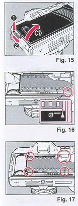
1. Press the back cover lock release button and slide the
back cover latch down to open the back cover. (Fig. 15)
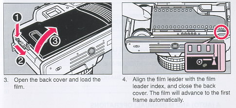
2. Load the film cassette into the film chamber and pull out
the film leader so that it extends past the film leader index.
(Fig. 16)
· If the film leader is pulled out more than necessary when
loading, the total number of exposures may be reduced.
3. Make sure that the film stays within the film guides, and
that the upper sprocket edge is under the guide plate. (Fig. 17)
|
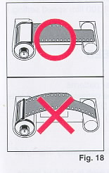
The film may not load properly if the film leader does not lie flat. Make
sure that the film lies flat as shown. (Fig. 18)
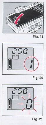 |
4. Close the back cover so that the back cover latch snaps
shut and returns to the original position. (Fig. 19) If the film
has been properly loaded, the film speed appears on the LCD
panel for about 2 seconds. Then, the exposure counter displays
"1". (Fig. 20)
· If the display on the LCD panel disappears, lightly press the
shutter button to turn on the power and update the LED panel.
· The ISO setting on the LCD panel can be checked by looking
through the film loaded window on the back cover of the camera
(applicable when the Data Back is not attached). The current ISO
setting can be determined also by turning the mode dial to
select the ISO User Setting mode.
5. If the film has not advanced properly or is not taken up onto
the film take-up spool, the exposure counter flashes "0". The
shutter will lock also to prevent you from taking a picture
until the film is loaded properly. (Applicable for DX coded
films only.) Reload the film by repeating steps 1-4 as described
above. (Fig. 21)
· If non-Ding films are loaded in this camera, no LCD warnings
will appear and the shutter can be released. (The film speed
must be set manually also. If not, non DX films will be set to
the default 100 film speed setting.)
|
 |
XII. SETTING THE FILM
SPEED AUTOMATICALLY
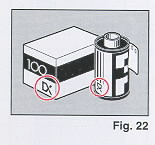
DX-coded films have black-and-silver patterns corresponding to
film speeds that the camera reads and sets automatically. Your
camera accepts DX films with speeds ranging from ISO 25-5000.
(Fig. 22)
DX Films
The film speed and the "ISO" indicator are briefly displayed on
the LCD panel.
For advanced applications, you may wish to raise or lower the
ISO speed of a DX-coded film. You can override the automatic ISO
setting manually between ISO 12 to 6400.
Refer to "lSO USER SETTING MODE" on page 32.
Non-DX Films
Non-DX films must be set manually. If not, the film will be
set to the default 100 film speed setting. For more information
on loading non-Ding films, refer to page 32.
|
A (AUTO) AND M (MANUAL) OPERATIONS
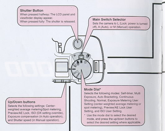
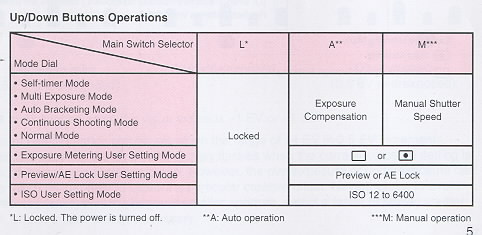
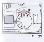
XIII. MAIN SWITCH SELECTOR--L/A/M
1. Set the main switch selector to the desired operation.
(Fig. 23)
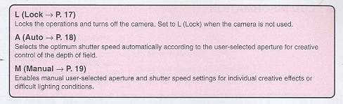
L (Lock)
Locks the operations and turns off the camera. Set to L
(Lock) when the camera is not used.
A (Auto ~ P. 18)
Selects optimum shutter speed automatically according to the
user-selected aperture for creative control of the depth of field.
M (Manual ~ P. 19)
Enables manual user-selected aperture and shutter speed settings for
individual creative effects or difficult lighting conditions.
· The LCD panel and the viewfinder display operate when A (Auto) or M
(Manual) is selected.
· If there is a film loaded in the camera, the film speed will be displayed
for the first 2 seconds.
2. Check the batteries.
· Refer to "MONITORING THE CONDITION OF THE BATTERIES" on page 14.
· If the main switch selector is set to L (Lock), the power will be
completely cut off. The LCD panel and the viewfinder display will not
operate.
· The following modes will be canceled when the main switch selector is set
to L (Lock).
· AE Lock setting (in the Preview/AE Lock User Setting mode)
· Self-timer mode
· To prevent unnecessary battery depletion, set the main switch selector to
L (Lock) when you are not using the camera.
Auto Power Off Function
If the camera controls. are not operated or camera operations** are not
performed for about 30 seconds, the display will disappear on the LCD panel.
At this time, if the shutter button is pressed lightly halfway, the display
will appear again. ~ All buttons, mode dial, and main switch selector. **
Shooting, film loading, and film rewinding.
· The mode settings selected before the display disappears, will not be
canceled.
· When the Auto Power Off function operates and the display disappears on
the LCD panel, only the following can be operated so that the display will
appear again: shutter button, manual rewind button and the main switch
selector. To set or change the mode settings, press the shutter button
halfway to operate the LCD panel.
· If the camera is not operated for about 10 seconds, the display inside the
viewfinder will disappear. By pressing the shutter button halfway, the
display will appear.
XIX. A (AUTO) OPERATION
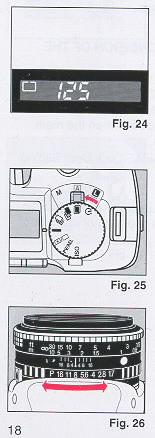 |
The camera is set to A (Auto) operation when the following
viewfinder display appears. Note that the viewfinder display may
vary slightly according to the current shutter speed and
settings (i.e., AE lock, exposure metering, flash, bulb, and
exposure compensation settings). (Fig. 24)
· If the LCD panel or viewfinder display is not operating, press
the shutter button halfway and the display will appear.
1. Set the main switch selector to A (Auto). (Fig. 25)
Make sure that the mode dial is set to either Self-timer
Multi Exposure, Auto Bracketing, Continuous Shooting, or Normal
mode.
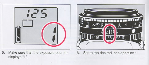
2. Set to the desired lens aperture. (Fig. 26)
· If the aperture is set to "P" or "A", turn the aperture
ring while pressing the ~ P" or "A" lock pin.
|
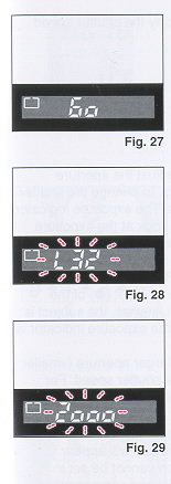 |
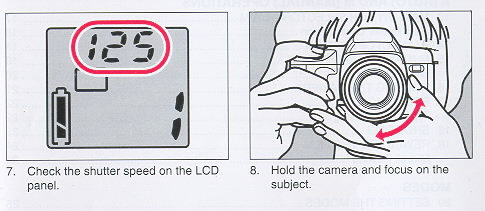
3. Check the LCD panel and look through the viewfinder and
make sure that the viewfinder display is operating. (Fig. 27)
· The shutter speed appears in the viewfinder display.
· The shutter speed flashes in the viewfinder display when
the subject is underexposed or overexposed. Under certain
conditions, a subject may be underexposed even when the slowest
shutter speed (i.e., 32 seconds) is set. "L32" flashes in the
viewfinder display. Use a flash unit, the Bulb function, or
simply select a larger aperture (smaller number aperture
setting) as necessary. Likewise, a subject may be overexposed
even when the fastest shutter speed (i.e., 1/2000 th second) is
set. "2000" flashes in the viewfinder display. Use a neutral
density filter or simply select a smaller aperture
(larger number aperture setting) as necessary. (Fig. 28, 29)
|
|
|
XV. M (MANUAL) OPERATION
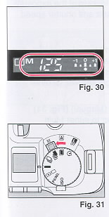 |
The camera is set to M (Manual) operation when the following
viewfinder display appears. Note that the viewfinder display may
vary slightly according to the current shutter speed and
settings (i.e., AE lock, exposure metering, flash, bulb, and
exposure compensation settings). (Fig. 30) Make sure that "M" is
displayed in the viewfinder display and that the lens aperture
is not set to "P" or "A".
1. Set the main switch selector to M (Manual). (Fig. 31)
Make sure that the mode dial is set to either Self-timer,
Multi Exposure, Auto Bracketing, Continuous Shooting, or
Normal mode.
|
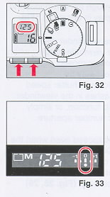 |
2. Press the up/down buttons to display the shutter speed you
wish to set. (Fig. 32)
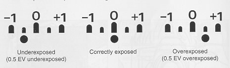
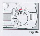
3. Look through the viewfinder and adjust the aperture
setting by turning the aperture ring. To change the shutter
speed, press the up/down buttons. The exposure indicator appears
in the viewfinder display. Look at the exposure indicator when
setting the aperture and shutter speed. When the dot (a) of the
exposure indicator is under the "O", the correct exposure is
set. (Fig. 33) The subject is underexposed when the dot (O) of
the exposure indicator is towards -1. Likewise, the subject is
overexposed when the dot (O) of the exposure indicator is
towards +1. For underexposed pictures, set a larger aperture
(smaller number aperture setting) or slower shutter speed. For
overexposed pictures, set a smaller aperture (large number
aperture setting) or faster shutter speed.
· If the viewfinder display is not operating, press the
shutter button halfway and the display will appear.
· Naturally, exposure compensation cannot be set in Manual
operation because the desired compensation can be deliberately
selected by looking at the exposure indicator when setting the
aperture and shutter speed.
|
 |
Bulb Function
If the shutter speed is set to "bulb" in Manual operation,
the shutter will remain open for as long as you keep the shutter
button pressed. This is referred to as bulb photography. Bulb
photography is used for shooting night scenes, or other images
with long exposure times.
1. Set the main switch selector to M (Manual) (Fig. 34) Make
sure that the mode dial is set to either Multi Exposure, or
Normal mode.
|
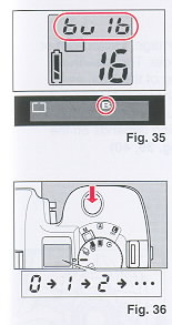 |
2. Press the up/down buttons to display "bulb" on the LCD
Panel. (Fig. 35)
· The Self-timer and Auto Bracketing modes are not applicable
when the shutter speed is set to "bulb".
· The "B" mark is also displayed in the viewfinder display.
3. Set to the desired lens aperture.
· If the aperture is set to "P" or "A", turn the aperture ring
while pressing the "P" or "A" lock pin.
4. Keep the shutter button pressed for as long as you wish the
shutter to remain open. (Fig. 36)
· If you remove your finger from the shutter button, the shutter
will close
· The exposure counter on the LCD panel will display the time
(in seconds) that the shutter has been open.
· To avoid camera shake, use a tripod and a release switch.
· If the battery runs out of power, the shutter may
prematurely close.
|
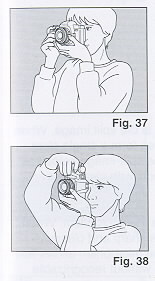 |
XVI. HOLDING THE CAMERA
To prevent camera shake, be sure to hold the camera properly
when shooting. Support the camera on the palm of your left hand
so that you can turn the focusing ring with your fingers. (Fig.
37)
With your right hand lightly grasp the grip and place your index
finger lightly over the shutter button. When pressing the
shutter button, grasp the grip firmly. Place your elbows against
your body. When shooting with the camera in a horizontal
position, or place your left elbow against your body when
shooting with the camera in a vertical position. (Fig. 38)
Place your forehead against the camera and look through the
viewfinder.
|
XVII. FOCUSING
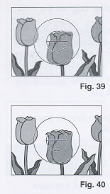 |
Focusing is achieved with the Split-image, Microprism or
Matte focusing screen in the viewfinder. The viewfinder image is
crucial for accurate focusing of the lens, and therefore greatly
influences image sharpness. Different photographic applications
often require different focusing screens. The optimum type of
focusing depends on the subject and the lens being used. (Fig.
39, 40)
|
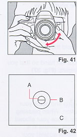 |
While looking through the viewfinder, focus by turning the
focusing ring. (Fig. 41)
Types of Focusing
A. Split-image The area inside the central circle is the split
image. When both images in the split-image area form a single
clear image, the subject is in focus. The split-image helps you
focus quickly and easily on subjects with clear lines or
contours. (Fig. 42)
B. Micropasm The area inside the outer circle is the microprism.
When the image stops "flickering" and is sharp and clearly
visible, the subject is in focus. The microprism allows fast and
precise focusing on subjects without recognizable lines or
contours. (Fig. 42)
|
C. Matte screen
The area outside the microprism is the matte screen. Focusing is done
by sight and requires practice as the transition from unsharp to sharp is
gradual rather than abrupt. The matte screen helps you focus precisely with
lenses of longer focal lengths as well as in the macro range. (Fig. 42)
· When you use a small aperture (large number aperture setting) with a lens
such as a zoom lens, half of the split image becomes dark. In this case, use
the matte screen to focus.
XVIII. SHOOTING
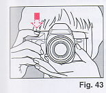 |
1. Press the shutter button halfway. (Fig. 43)
· The LCD panel and viewfinder display operate.
· The shutter button can be pressed in two ways. If it is
pressed halfway, the LCD panel and the viewfinder display
operate. If it is pressed fully, the shutter is released.
· If the camera is not operated for about 10 seconds, the
display inside the viewfinder will disappear. By pressing the
shutter button halfway, the display will appear.
· If the camera is not operated for about 30 seconds, the
display on the LCD panel will disappear. By pressing the shutter
button halfway, the display will appear.
|
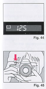 |
2. Confirm that the viewfinder display is operating. (Fig.
44)
Fig. 44 indicates the viewfinder display in Auto operation.
The number denotes the current shutter speed. Note that the
viewfinder display may vary slightly according to the current
operation (i.e., Auto or Manual) and settings (i.e.,
AE lock, exposure metering, flash, bulb, and exposure
compensation settings).
· When a slow shutter speed has been set, use a tripod to
prevent camera shake.
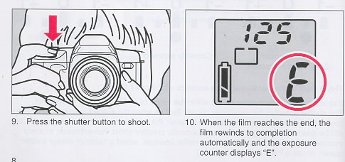
3. Press the shutter button. (Fig. 45)
· The film advances when the shutter is released.
|
XIX. REWINDING THE FILM
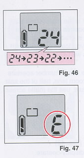 |
1. When the film has reached the end, the film rewinds to
completion automatically while the exposure counter counts down.
(Fig. 46)
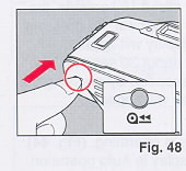
· When the film is completely rewound, the exposure counter
displays "E". (Fig. 47)
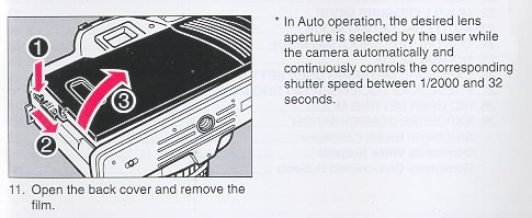
2. While pressing the back cover lock release button, slide
the back cover latch down and open the back cover.
3. Remove the film.
· When you are in a quiet location and the noise produced
during film rewinding is disturbing, set the main switch
selector to L (Lock) to turn off the power. Rewinding will be
temporarily stopped. When the main switch selector is set to A
(Auto) or M (Manual), the film will resume rewinding.
· If the manual rewind button is pressed while the film is
rewinding, the film leader will not be rewound completely so
that a portion of the film leader protrudes from the film
cassette.
|
 |
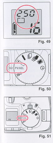
Midroll Rewind
Press the manual rewind button. (Fig. 48)
· When removing the film, be careful not to touch the shutter
with your fingers or with the edge of the film.
· The shutter cannot be released when "E" is displayed on the
LCD panel.
· It is sometimes possible to take more exposures than the
specified number indicated on the box of the film. However,
these "extra" exposures may be overlapped or cut off.
|
MODES
XX. SETTING THE MODES
 |
Use the mode dial to select the desired mode (i.e., Self
timer, Multi Exposure, Auto Bracketing, Continuous Shooting,
Normal, Exposure Metering User Setting, Preview/ AE Lock User
Setting, and ISO User Setting modes). Press the up/down buttons
to select the desired setting (i.e., Exposure Metering User
Setting, Preview/AE Lock User Setting, and ISO User Setting) and
to set the shutter speed in Manual operation or exposure
compensation in Auto operation. A For a brief explanation, refer
to the "FUNCTION MAP" on pages 4-5.
For more information on modes and settings, refer to the
appropriate sections for each mode.
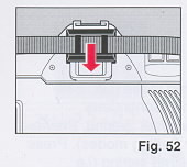
The settings are displayed on the LCD panel. (Fig. 49)
· If the LCD panel or viewfinder display is not operating,
press the shutter button halfway and the display will appear.
The modes cannot be set when the display is not operating
1. Turn the mode dial to select the mode you wish to set.
(Fig. 50)
2. Press the up/down buttons and set or adjust the value of
the mode you have selected. (Fig. 51 ) For more information,
refer to "Up/Down Buttons Operations" on page 5.
|
 |
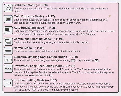
XXI. SELF-TIMER MODE
1. After focusing, slip the viewfinder cap attached to the
strap over the viewfinder eyepiece as necessary. (Fig. 52)
· The viewfinder cap is used to avoid incorrect exposure due
to stray light which may enter the viewfinder eyepiece. This is
to ensure that the metering system is not adversely affected.
· The Self-timer mode is not only useful for self-portraits
but also for shake-free exposures with slow shutter speeds.
|
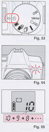 |
2. Turn the mode dial to select A) (Self-timer mode).
(Fig. 53)
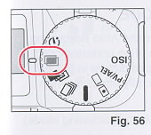
3. Press the shutter button.
· When the self-timer has been activated, the self-timer LED
will start flashing and about 10 seconds later, the shutter will
be released. The self-timer LED remains lit for the last 2
seconds before the shutter is released. (Fig. 54)
· To cancel the Self-timer mode after pressing the shutter
button, turn the mode dial to select another mode, or set the
main switch selector to L (Lock) to turn off the power.
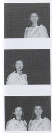
· The exposure counter on the LCD panel indicates the number
of seconds remaining before the shutter is released. (Fig. 55)
· The Self-timer mode is not applicable when the shutter
speed is set to "bulb".
|
 |
XXII. MULTI EXPOSURE MODE
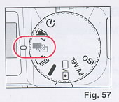
1. Turn the mode dial to select (Multi Exposure mode).
(Fig. 56)
|
 |
2. Press the shutter button as many times as necessary to
take several exposures on the same frame.
· The film will not advance and the exposure counter number
will remain the same.
· To cancel the Multi Exposure mode, turn the mode dial to
select another mode, or set the main switch selector to L (Lock)
to turn off the power.
· When developing negative films, make sure that you indicate
that the film contains multi exposure shots where applicable.
The multi exposed shot may be mistaken for an error and may not
be printed.
|
XXIII. AUTO BRACKETING MODE
 |
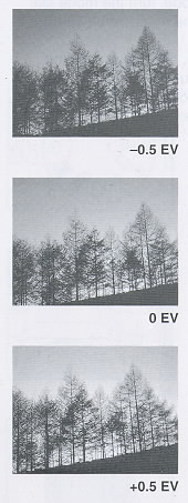
When the shutter button is pressed in the Auto Bracketing
mode, the camera will take 3 frames of an underexposed, a
correctly exposed, and an overexposed picture in 0.5 EV
increments. Auto Bracketing is especially effective when using a
reversal (slide) film.
|
 |
1. Turn the mode dial to select (Auto Bracketing mode).
(Fig. 57)
2. Press the shutter button.
· The camera will take 3 frames in the following order:
underexposed (-0.5 EV), correctly exposed (O EV), and
overexposed (+0.5 EV).
· To cancel the Auto Bracketing mode, turn the mode dial to
select another mode.
· When the Auto Bracketing mode is combined with exposure
compensation or AE lock, the exposure range will be based on the
selected exposure compensation value or the locked exposure
value respectively. For example, when exposure compensation or
the locked exposure value is -1.0 EV: the exposure range will be
-1.5 EV, -1.0 EV, and -0.5 EV.
· The Auto Bracketing mode is applicable for Manual operation
also.
· The Auto Bracketing mode cannot be combined with flash
photography (i.e., Ricoh flash units such as the Speedlite 303P,
323, 403P, etc.).
· The Auto Bracketing mode is not applicable when the shutter
speed is set to "bulb".
|
XXIV. CONTINUOUS SHOOTING MODE
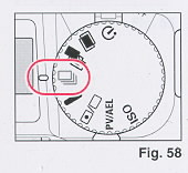 |
Continuous shooting occurs for as long as you press the
shutter button in the Continuous Shooting mode.
1. Turn the mode dial to select  (Continuous Shooting mode). (Fig. 58)
2. Press the shutter button. Continuous shooting is enabled
as long as the shutter button is pressed.
· To cancel the Continuous Shooting mode, turn the mode dial
to select another mode, or set the main switch selector to L
(Lock) to turn off the power.
|
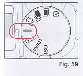 |
XXV. NORMAL MODE
When done with using other modes, set the camera to the Normal
mode. Under normal conditions, the camera should be set to the
Normal mode.
1. Turn the mode dial to select --
(Normal mode). (Fig. 59) When you do not wish to operate the
Self-timer, Multi Exposure, Auto Bracketing, or Continuous
Shooting mode, and do not require to change the Exposure
Metering User Setting, Preview/AE Lock User Setting, or ISO User
Setting mode, set the camera to the Normal mode.
2. Press the shutter button.
|
 |
XXVI. EXPOSURE METERING USER SETTING MODE
This camera has 2 types of exposure metering systems:
center-weighted average metering and spot metering. Choose the
appropriate metering system according to the situation or
subject you are shooting.
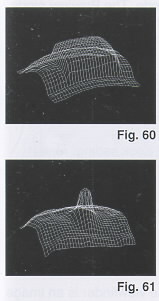
Center-weighted average metering This system measures
the viewing area, emphasizing the center portion. This metering
system is ideal for general shooting and landscape shooting.
(Fig. 60)
Spot metering This system only measures the central
spot (inside the microprism area). This metering system is
effective when there is a wide contrast between the subject and
the background, or when you wish to emphasize a section of the
subject (i.e., portrait shooting in backlit conditions, subjects
on a stage, etc.). (Fig. 61)
|
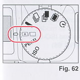 |
1. Turn the mode dial to select  (Exposure Metering User Setting mode). (Fig. 62)
 |
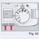 |
2. Press the up/down buttons to select either [ ] (spot l
metering) or [*] (center-weighted average metering). (Fig. 63)
3. To change the current exposure metering setting, repeat steps
1 and 2 again.
|
 |
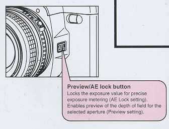
XXVII. PREVIEW/AE LOCK USER SETTING MODE
The Preview/AE Lock User Setting mode allows setting for the
Preview mode or the AE Lock mode. The Preview mode enables the
preview of the depth of field for the selected aperture. The AE
Lock mode locks the exposure value for precise exposure
metering.
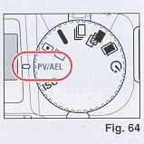
1. Turn the mode dial to select PV/AEL (Preview/AE Lock User
Setting mode). (Fig. 64)
|
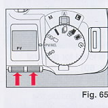 |
2. Press the up/down buttons to
select either PV (Preview) or AEL (AE Lock). (Fig. 65) To change the
current Preview/AE Lock setting, repeat steps 1 and 2 again. |
 |
Preview
Normally, the image seen through
the viewfinder is an image with the aperture open. The Preview
mode sets the actual aperture you have selected allowing you to
confirm the depth of field of the image.
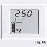
1. Make sure that PV (Preview) is selected for the Preview/
AE Lock User Setting mode as described above. "PV" is displayed
on the LCD panel in all modes except the Exposure Metering User
Setting and ISO User Setting modes when Preview is selected.
(Fig. 66)
|
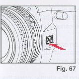 |
2. While looking through the viewfinder, press the preview/
AE lock button. (Fig. 67)
· The aperture will be set to the aperture opening you have
selected and you can confirm the areas that are focused.
· The viewfinder image will darken when the Preview/AE lock
button is pressed.
|
 |
AE Lock
The AE Lock mode locks the
exposure value for precise exposure metering. With the AE Lock
mode, you can precisely meter a subject detail that is not
located in the center of the viewfinder, and cope with
high-contrast subjects and backlit situations when used in
combination with exposure compensation.
· If you cannot get close to the subject, it is recommended
that the Exposure Metering User Setting mode be set to spot
metering for optimum AE lock results.
1. Make sure that AEL (AK Lock) is selected for the Preview/
AE Lock User Setting mode as described above.. "AEL" is
displayed on the LCD panel in all modes except the Exposure
Metering User Setting and ISO User Setting modes when AE lock is
selected.
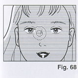
2. Bring the camera as close to the subject as necessary so
that the exposure will not be affected by the background.
(Fig. 68)
|
 |
· If the LCD panel is not operating, press the shutter button
halfway and the display will appear. The mode cannot be set when
the LCD panel is not operating.
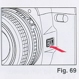
3. Press the Preview/AE lock button. (Fig. 69) The exposure
value is locked. The "AEL" mark flashes in the viewfinder
display and "AEL" remains lit on the LCD panel in all modes
except the Exposure Metering User Setting and ISO User Setting
modes.
|
4. Compose your picture and press the shutter button.
The picture is taken with the locked exposure value. When the picture is
taken, AE lock will be canceled and the "AEL" mark will disappear.
· If the aperture is changed while an exposure value is locked in Auto
operation, the camera will adjust the shutter speed to correspond to the
exposure value that is locked.
· To cancel AE lock before releasing the shutter, press the preview/AE
lock button again or set the main switch selector to L (Lock) to turn off
the power.
· If the preview/AE lock button is kept pressed while shooting, it is
possible to shoot repeatedly with the locked exposure value.
XXVIII. ISO USER SETTING MODE
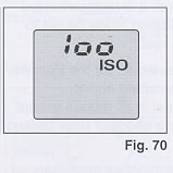 |
The ISO User Setting mode is set when "ISO" is displayed on the
LCD panel. (Fig. 70)
The ISO User Setting mode allows setting for ISO manual
override of the film for advanced applications. Under normal
conditions, the camera sets the ISO film speed for DX-coded
films ranging from ISO 25 to 5000 automatically (ISO 12 to 6400
for manual override setting).
The manual ISO setting has priority over the automatic DX
coded setting.
This mode is used to set the film speed for non-Ding films,
or to set a different film speed than that specified for
DX-coded films.
|
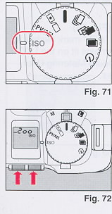 |
1. Turn the mode dial to select ISO (ISO User Setting mode).
(Fig. 71)
2. Press the up/down buttons to set the desired film speed.
(Fig. 72)
· The exposure difference between the automatic DX coded setting
and the manual override film speed setting is indicated by the
"+" and "-".
· The film speed you have set will be displayed for about 2
seconds when the main switch selector is set to A (Auto) or M
(Manual), and when the film is loaded.
· Non-DX films must be set manually. If not, the film will be
set to the default 100 film speed setting.
|
XXIX. EXPOSURE COMPENSATION
 |
Exposure compensation is applicable for the Self-timer mode,
Multi Exposure mode, Auto Bracketing mode, Continuous Shooting
mode and Normal mode in Auto operation only. For more
information, refer to "Up/Down Buttons Operations" on page 5.
When there is excessive contrast between the subject and the
background, the subject may be underexposed (dark) or
overexposed (light). When this occurs, or when you cannot bring
the camera close to the subject, exposure compensation can be
used. (Use the AE lock when you can bring the camera close to
the subject. Refer to page 31.) Also, an image may come out gray
when white or black is dominant. The light and dark colors of
your picture can be shot correctly by using this mode. You can
also shoot underexposed or overexposed pictures intentionally.
Exposure compensation can be set within the range of _4.0 EVA in
0.5 EVA increments
· Naturally, exposure compensation cannot be set in Manual
operation because the desired compensation can be deliberately
selected by looking at the exposure indicator when setting the
aperture and shutter speed.
Shooting in Backlit Conditions In backlit
conditions the subject will be underexposed because of the very
bright background. Set the exposure compensation to a plus (+)
value depending on the lighting conditions.
|
 |
Dominantly White
Subjects
If a dominantly white subject is
photographed, it will be underexposed and appear dark. In addition,
white areas will turn out gray. Set the exposure compensation to a
plus (+) value depending on the lighting conditions. |
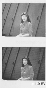 |
Dominantly Dark-colored
Subjects
If a dominantly dark-colored subject is shot,
the whole image will be overexposed, making the subject light
(white) and dark-colored areas will come out gray. Set the exposure
compensation to a minus (-) value depending on the lighting
conditions. |
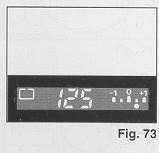 |
· When the exposure indicator is
displayed in the viewfinder display as shown in the illustration,
the exposure compensation is set. The exposure indicator displays
the selected exposure compensation value. (Fig. 73) The LCD panel
displays the exposure compensation value also. Press the shutter
button halfway and press the up/down button to display the exposure
indicator in the viewfinder display and the exposure compensation
value on the LCD panel. |
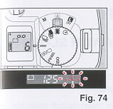 |
1. Press the up/down buttons until the exposure indicator is
displayed. (Fig. 74) The exposure indicator is displayed in the
viewfinder display. The exposure compensation value is displayed
on the LCD panel also.
· The exposure indicator appears flashing in the viewfinder
display. This allows you to set the exposure compensation while
looking through the viewfinder.
· If you do not make any changes (i.e., exposure compensation
remains set to 0 EVA) within 5 seconds after pressing the up/down
buttons, the exposure indicator in the viewfinder display will
disappear. If you are adjusting a previous exposure compensation
value, the exposure indicator will remain in the viewfinder
display.
|
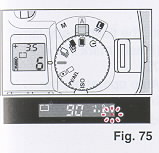 |
2. Press the up/down buttons to set the desired exposure
compensation value. Each time the up or down button is pressed,
the exposure compensation value increases or decreases in 0.5
EVA
increments. Press and hold down the up or down button to
increase or decrease the exposure compensation value
continuously within the range of +4 EVA in 0.5 EVA increments.
· The dot (A) of the exposure indicator flashes when the
exposure compensation exceeds +1 EVA or-1 EVA. (Fig. 75)
· When you have finished shooting with exposure compensation, be
sure to restore the exposure compensation value to 0 EVA.
|
FLASH PHOTOGRAPHY
XXX. FLASH PHOTOGRAPHY WITH SL-303P, SL-403P
 |
When you use any of the above Ricoh dedicated flash systems,
you can enjoy flash photography.*
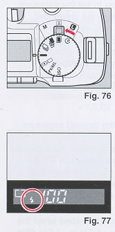
1. Set the flash unit to "A" and set the main switch selector to
A (Auto). (Fig. 76)
2. Set the lens aperture to the aperture value designated by the
flash unit according to the ISO setting of your camera
· Be sure to stay within the recommended flash range for the
speed of the film you are using. If you are too close to the
subject, your pictures may look too light; if you are beyond the
maximum distance, your pictures may look too dark
3. When the flash unit is fully charged, the flash-ready lamp on
the flash unit lights and the ~ (Flash) mark in the viewfinder
display appears. (Fig. 77)
When the flash unit is charged in Auto operation, the shutter
speed is set to 1/100 automatically.
· The subject may be overexposed when "100" flashes in the
viewfinder display.
|
4. Press the shutter button.
· Make sure that the camera is not perpendicular to reflective backgrounds
such as mirrors or other shiny surfaces. The flash will be reflected back to
the camera and cause a bright glare spot in your picture. The reflected
glare may also cause underexposure. Take pictures at an angle to shiny
surfaces to minimize flash reflections.
· For manual flash photography, slide the switch lever of the flash unit to
"M", and set the shutter speed between L32 to 90. (If the shutter speed is
set between 1/125 - 1/2000, the shutter speed will be set to 1/100
automatically.) The user-selected shutter speed flashes on the LCD panel,
and "100" appears in the viewfinder display. The dot (A) of the exposure
indicator below +1 flashes in the viewfinder display for manual flash
photography.
For Ricoh SL-323, follow the instructions for "FLASH PHOTOGRAPHY WITH FLASH
UNITS OTHER THAN RICOH".
XXXI. FLASH PHOTOGRAPHY WITH FLASH UNITS OTHER THAN RICOH
1. Set the flash unit to Auto mode and set the shutter speed below 1/90.
2. Set the lens aperture to the aperture value designated by the flash unit
according to the ISO setting of your camera.
OTHERS
XXXII. INFRARED FILM
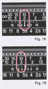 |
Always readjust your focus to the infrared focusing mark when
using infrared films and infrared filters. This is necessary
because the infrared rays have longer wave lengths than the
visible light rays you see and focus with, and the camera lens
focuses them slightly further back inside the camera. Therefore
visual focusing cannot be accurate without adjustment.
1. Attach the infrared filter and focus on the subject. Read
the indicated distance off the lens barrel. (Fig. 78)
2. Shift that distance setting over to the red infrared index
mark. Set the exposure in accordance with the instructions for
the film. (Fig. 79)
(webmaster: If you want RI images, go digital. There
are many options available.
|
XXXIII. DIOPTRIC LENSES
The viewfinder eyepiece has a built-in -1 correction lens (suitable for most
normal vision). If a dioptric lens is fitted, you would not have to wear
eyeglasses when taking pictures. Slip the lens in the groove of the
viewfinder eyepiece. Dioptric lenses are available in 7 types: -4, -3, -2,
-1, +1, +2 and +3.
· Some forms of astigmatism, etc., may make dioptric eyepiece correction not
possible. Please check with your optician for a recommendation based on your
prescription.
XXXVI. INTERCHANGEABLE VIEWFINDER SCREENS
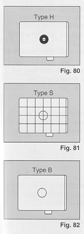 |
Ricoh offers a choice of 3 viewfinder screens to suit your
needs or preference. Each features Ricoh's Acu-Bright mat for
optimum brightness and easier focusing in dim light.
Horizontal Split Type Screen (MH type) This screen is
normally installed. Recommended for general shooting. (Fig. 80)
Grid Matte Type Screen (MS type) A matte screen with
horizontal and vertical lines. This screen facilitates
composition of your photograph. (Fig. 81)
All Matte Type Screen (MB type) For general shooting
and close-up photography. Also recommended when focusing is
difficult with a split image. (Fig. 82)
|
XXXV. RELEASE SWITCH
By using the separately sold release switch, the shutter can be released
from a distance.
1. Set the main switch selector to L (Lock) to turn off the power.
· The shutter may release if the release cable is connected to the
camera when the power is on.
2. Connect the release switch to the remote control socket of the camera.
3. Set the main switch selector to A (Auto) or M (Manual).
4. Press the release switch to shoot.
XXXVI. CARE OF BATTERIES
· This camera is equipped with precision electronic parts. To ensure
optimum performance, use high quality alkaline batteries.
· The capacity of the batteries depends on the brand and type of
batteries used.
· Before installing, be sure to clean all moisture, oil, and grease off
all battery contact surfaces in order to avoid future problems of corrosion
and poor electrical contact.
· Remove batteries when the camera is not used for a long period of time.
· Dispose of batteries properly. Do not throw them into fire or expose to
high temperature.
· In cold conditions, battery power decreases and may not be sufficient
to operate the camera. Avoid using the camera in low temperatures.
Notes on Film
· Use a loaded film promptly and have it developed as soon as it is removed.
Leaving a film loaded inside the camera for an extended period of time will
lead to the deterioration of the film, etc.
XXXVII. DATA BACK 7
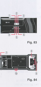 |
The Ricoh XR-X3000D is standard equipped with the Data
Back 7. To use the date imprinting feature for the Ricoh
XR-X3000, purchase the separately sold Data Back 7.
Nomenclature of the Date Imprinting Feature
(Fig. 83, 84)
(1) Display Panel
(2) Month Indication (M)
(3) imprint Mark ( _ )
(4) Mode Button
(5) Select Button
(6) Set Button
(7) Locating Pin (Connecting pin)
(8) Battery Cover
(9) Battery Cover Retaining Screws
(10) Data Back Contacts
|
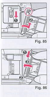 |
Attaching the Data Back 7
1. Open the back cover and push down the release pin on the
back cover to remove. (Fig. 85)
2. Attach the Data Back 7 to the camera while pushing down
the release pin on the Data Back 7. (Fig. 86)
· To remove the Data Back 7, follow the same instruction
in step 1.
|
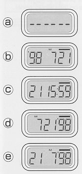 |
Selecting the Imprinting Mode
Each time the Mode button is pressed, the display changes as
shown below.
<Examples of Date Imprinting>
Date imprinting can be divided into five types: date, time,
and no imprinting.
(a) No imprinting
(b) Date (Year/Month/Day)
1998 July 21st
(c) Time (Day/Hour/Minute)
21st 15:59
(d) Date (Month/Day/Year)
July21st, 1998
(e) Date (Day/Month/Year)
21 st July, 1998
|
 |
Date Imprinting Location
Date imprinting appears on the lower right hand corner of the
photograph. (Fig. 87)
|
Checking Imprinting
After shooting, the imprint mark
-- flashes on the display panel for a few seconds to confirm proper
imprinting. The imprint mark -- and the letter "M" are
not imprinted on the photograph.
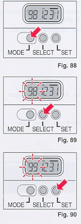 |
Resetting the Date and Time (Fig. 88, 89, 90)
1. Each time the Select button is pressed, the flashing digits
change in the following order: Year, Month, Day, Hour, Minute
and Colon (:).
2. When the digits to be reset flash, press the Set button
until the desired digits appear. When the Set button is kept
pressed, the digits change rapidly.
3. Imprinting is not possible while the Data Back is being
reset. When resetting is complete, press the Mode button until
the imprint mark _ appears on the display panel.
Accurately Setting the Seconds
1. Press
the Mode button to display the time (Day/Hour/ Minute).
2. Press the Select button so that the colon (:) flashes.
3. Press the Set button accordingly to set the seconds to 0.
4. Press the Mode button.
|
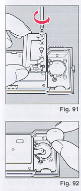 |
Battery Replacement
1. Open the back cover.
2. Remove the battery cover retaining screws from the Data Back
battery cover with a small (+) or (-) screwdriver.
Remove the battery cover. (Fig. 91)
3. Remove the battery.
4. Load the new battery with the side marked (+) facing
upwards. Then, close the battery cover using the (+) or (-)
screwdriver. (Use lithium battery CR2025. The service life is
about 3 years.) (Fig. 92)
· When the battery is exhausted, the imprinted digits
become faint. At that time, replace the battery.
· Do not open the battery cover except when replacing the
battery.
· Keep the battery out of reach of children. If a child
swallows the battery, contact your doctor immediately.
|
Notes on Date Imprinting Feature
· At temperatures below 0°C (32° F), the battery ,performance deteriorates.
The date imprinting feature may not function correctly and imprinting may
become impossible.
· When the battery is replaced, the display panel sometimes shows the wrong
digits. Reset the digits for correct indication.
· The date is sometimes illegible if it is imprinted on the following
objects.
(1 ) "Warm" colored objects, such as red, yellow, orange, etc.
(2) Objects with details similar in size to the imprinted date (gravel,
leaves, etc.)
(3) Objects of high luminance (sky, white wall, etc.)
· Imprinting is not possible in the following modes. (1 ) Print Off mode (2)
Reset mode
XXXVIII. PROPER CARE OF YOUR CAMERA
· If there is dirt on the lens or mirror surface, do not attempt to remove
it with your fingers. Use a blower to blow the dust away, or wipe the
surface gently with a camera lens tissue or a soft cloth.
· Excessive shock, humidity or salt may cause camera malfunction. When you
use the camera at the beach, in a corrosive atmosphere, or in a place where
chemicals are used, wipe it off carefully.
· Do not expose the camera and film to extreme temperatures.
· Do not leave your camera in your car at the beach, in the desert, or in
other extremely high temperature conditions to prevent possible damage to
the camera.
· When using a tripod, do not try to force a long screw into the socket.
(The screw length should be less than 5.7 mm (1 /4 ).
· Store the camera away from humidity and in a dust-free place.
· This camera is not waterproof. If it comes into contact with any kind of
liquid (i.e., water, rain, drink, etc.), the electrical and metal parts will
rust and cause damage to the camera. Contact a Ricoh Camera Service Center
if your camera has been exposed to any liquid.
· Take care not to expose the camera to sudden changes in temperature, as
this may cause condensation on the lens, film, or inside the camera which
may lead to the malfunction of the camera.
· Do not place the camera near equipment that has strong magnetic fields
such as a television or radio.
XXXIX. MAJOR SPECIFICATIONS .
Type: 35mm SLR camera with focal plane shutter, Automatic
and Manual exposure controls
Mount: Ricoh system K mount
Shutter: Electronically controlled, vertically moving
focal plane shutter;
Automatic: 1/2000 sec.-32 sec.
Manual: 1/2000 sec.-32 sec., Bulb
Exposure Coupling Range: EV 0-18 (ISO 100 with standard
F1.4 lens)
Photographic Modes: Aperture-priority automatic exposure
mode Manual exposure mode
Self-timer: Electronically operated 10 sec. delay with
LED indicator
Viewfinder: Field of view: 91% horizontally and
vertically Magnification: 0.80x (with 50mm standard lens)
Finder display: AE lock, exposure indicator, flash mark, exposure
metering modes, shutter speed, bulb, and Manual operation
Focusing Screen: Interchangeable type, horizontal
split-image spot in microprism band surrounded by mat.
Exposure Metering System: Two selectable TTL full open metering
systems
(1) Center-weighted average metering (LV 0-LV 18.0: F1.4 lens)
(2) Spot metering (LV 4.0-LV 18.0: F1.4 lens)
Sync Speed: 1/100 sec.
Exposure Compensation: +4 EV
Flash Contact: Hot shoe
Film Loading: Ricoh Auto-load system, automatic 1st
frame setting
Film Advance: Automatic with a built-in motor, two
selectable modes:
Normal (single) and Continuous Shooting (approx. 0.7 sec./frame)
Film Rewind: Automatic rewind at the end of film, manual
rewind possible, film can be rewound so that a portion of the film leader
protrudes from the film cassette
ISO Setting: ISO 25-5000 DX-coded,
ISO 12-6400 Manual (Manual override possible)
Preview: - Electronic preview button
Remote Control: Remote control socket
Automatic Bracket Mode: +0.5 EV
Back Cover: Removable (Data Back 7 or Data Back 3 for
date imprinting)
LCD Display: Exposure counter, ISO, battery indicator,
shutter speed, center-weighted average/spot metering mark, time for bulb,
remaining seconds for self-timer, AEL (AK Lock), PV (Preview), exposure
compensation value (+4.0 EV in 0.5 EV steps)
Main Switch Selector:
(1) L (Lock)
(2) A (Auto)
(3) M (Manual)
Mode Dial: (1) Self-timer
(2) Multi Exposure
(3) Auto Bracketing
(4) Continuous Shooting
(5) Normal
(6) Exposure Metering User Setting
(7) Preview/AE Lock User Setting
(8) ISO User Setting
Power Source: Four alkaline batteries
Dimensions: Approx. 151 x 94.5 x 62 mm/ 5.9 x 3.7 x 2.4 inches
(WxHxD)
Mass Weight: Approx. 480 g/17 oz. without
batteries