and historical purposes, all rights reserved.
This page is copyright© by
This page may not be sold or distributed without
the expressed permission of the producer.
I have no connection with any camera company.
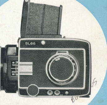
Rolleiflex SL66
Rolleiflex SL66 SE / E Bedienungsanleitung
Camera Manual
7-15-2014
This camera manual library is for reference
and historical
purposes, all rights reserved.
This page is copyright© by
![]() - NJ.
- NJ.
This page may not be sold or distributed without
the expressed
permission of the producer.
I have no connection with any camera company.
On-line camera manual library
If you find this manual
useful,
CLICK HERE TO
CONTINUE TO
Rolleiflex SL66 PDF version
Rolleiflex SL66 PDF
Rolleiflex SL66 SE / E Bedienungsanleitung
CLICK HERE TO GO TO
how about a donation of $3 to:
M. Butkus, 29 Lake Ave.,
High Bridge, NJ 08829-1701
and send your
e-mail address
so I can thank you.
Most other places would charge
you $7.50 for a electronic copy
or $18.00 for a hard to read Xerox copy.
This will help me to continue to host this site,
buy new manuals,
and pay their shipping costs.
It'll make you feel better, won't
it ?
If you use Pay Pal, use the link below.
Use the above address for a check,
M.O. or cash.
Rolleiflex SL66 HTML MANUAL
made from HTML page - better printing
made direct from manual
Rolleiflex SL66 X
Bedienungsanleitung
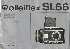
ROLLEIFLEX SL66 Box BOOKLET